金属增材制造技术,又称为金属3D 打印技术,被列入未来经济的十二大颠覆技术之一, 是工业4.0 时代的关键技术[1-2]。 增材制造技术是通过三维数字模型采用材料逐层累加来制造零件的技术。 相对于传统的材料去除技术, 增材制造技术是一种“自下而上”的累加方法。由于这一特点,金属增材制造不需要传统的模具、刀具、夹具及多道加工工序,通过三维重构可以快速而准确地制造任意形状的工件,具有设计自由度高、能够制造复杂部件和定制化产品等优势[3-4]。目前,金属增材制造广泛应用于航空航天、医疗、能源、自动化、海洋等领域[5-6],用于制造诸如定制化的金属植入物[7]、带有内部冷却通道的涡轮叶片[8]、发动机和涡轮的歧管以及具有优化强度重量比的点阵结构和桁架网络[9]等。
在金属增材制造过程中,高能热源快速扫过材料表面,材料局部经历快速熔化-凝固过程,导致熔池区域具有极高的温度梯度和冷却速率[6,10],产生与传统工艺不同的微观组织。 同时,合金成分及工艺参数的选择会对熔池的形貌、热循环、凝固过程中的冷却速率以及温度梯度造成影响,从而影响微结构的演化,最终影响工件的性能。 因此,由于成型过程不同,基于传统工艺开发的合金体系及相关工艺参数不再适用于增材制造过程[11]。 为了制备高性能产品,开发金属增材制造专用的合金成分及相关工艺至关重要[12-15]。 长期以来,对增材制造用合金的成分与工艺开发主要依赖于传统的“试错法”[16-20]。 试错法需要通过不断的实验尝试来调整合金成分及工艺参数获得所期望的性能特征。 然而,金属增材制造制备过程冶金反应复杂且需调控的工艺参数多[21],若要对大量合金成分在不同工艺参数下进行系统的实验研究, 则需要消耗大量的人力和财力,且实验研究周期长, 限制了金属增材制造的快速发展[22-24]。
随着凝固理论和计算机技术的逐渐完善和成熟,通过数值模拟的方法可以实现对材料凝固过程微结构演变的描述。 对凝固过程中微结构组织进行数值模拟可以系统地研究合金的凝固组织随工艺参数的演变规律, 从而更好地对金属增材制造过程进行设计,获得高性能产品。 常用的微结构模拟方法包括相场法[25-29]、蒙特卡洛法[30-32]和元胞自动机[12,33-36]。蒙特卡洛法是一种基于概率统计理论的数值方法,只能模拟晶粒的大小和形状。 元胞自动机是一种网格动力学模型,具有模拟复杂系统时空演化过程的能力[37],可以准确模拟枝晶形貌及晶粒取向演化[38-40]。 而相场法除了能获得晶粒或粉末颗粒的演化、枝晶的形状、尺寸等信息外,还能定量描述凝固过程中的溶质分布和显微偏析等[41]。因此,在金属增材制造微结构模拟中常采用相场法对微结构演化进行研究,探究不同合金成分和不同工艺参数对凝固微结构的影响,为合金成分及工艺设计提供指导。
金属增材制造涉及传热与传质、相变、晶粒生长、熔体流动多个物理过程,微结构演化的影响因素复杂,这给增材制造合金设计和性能调控带来了挑战。 相场法采用序参量描述气/液/固相、晶粒形状/取向等各种复杂的微结构,并能直接引入描述各种物理过程的场变量(如应力/应变、熔体流速、温度、浓度、电/磁场等),在增材制造过程结构模拟与机理探究方面显示出巨大优势。因此,本文简要介绍了相场法的发展与分类, 综述了近年来相场方法在金属增材制造领域的研究进展, 并详细分析不同相场模型在金属增材制造微结构演模拟中的优势与不足。最后, 针对相场法在金属增材制造微结构演变的高效、定量模拟乃至合金设计中的应用进行展望,并指出发展方向。
1 相场法简介
自90 年代初以来,相场法广泛应用于各种材料过程的微结构演变模拟[28,42-46]。 相场法选取一组合适的场变量构建体系的自由能泛函(包括体系的化学自由能、界面能等),基于变分原理在数值计算过程中使体系的自由能达到最小, 从而实现了体系微结构演变的模拟。 相场法引入场变量描述界面的变化, 避免了传统的尖锐界面模型中需要追踪相界面位置的数值困难,可以进行复杂微结构的三维模拟[47-48]。 相场法主要分为两大类[49],一类是由Chen[50]和Wang[51]基于Khachaturyan 提出的微观理论发展而来的微观相场模型, 这类相场主要应用于固态相变过程,如从无序基体中析出有序金属间相、马氏体相变等。 此外,Chen 将序参量推广到了多域结构(multi-domain structure), 用于研究多晶结构的晶粒生长及晶粒长大过程[52-58]。 另一类是连续相场模型,由Langer[59]基于Hohenberg 等[60]提出的model C 发展而来,这类相场模型主要应用于凝固过程,如研究复杂枝晶形貌的生长、溶质元素偏析等[25,28]。 本章主要介绍用于凝固过程的连续相场模型。
常用的连续相场模型包括Wheeler-Boettinger-Mc Fadden(WBM)相场模型[61-62]、Kim-Kim-Suzuki(KKS)相场模型[63-64]、Karma 相场模型[48,65-66]、多相场模型[29,67-68]等。Wheeler 等[61-62]基于热力学守恒定律将纯物质的相场模型推广到了二元合金体系, 建立了WBM 相场模型, 该模型可以再现高凝固速率下的溶质截留现象。 不足的是,WBM 相场模型[61]假设界面上的任意点都是具有相同成分的固相和液相混合物, 从而导致界面上出现不连续的化学势跳跃;此外,WBM 相场模型的模拟界面厚度也会影响模拟结果。针对WBM 相场模型存在的缺陷,Kim 等[63]在WBM 相场模型的基础上进行了修正, 并发展了KKS 相场模型。KKS 相场模型认为界面上每个点具有独立的固相成分和液相成分, 在局部平衡的假设下,每个点固相与液相具有相同的扩散势。 KKS 相场模型虽然在热力学上接近真实体系的能量,但是由于计算效率低, 不能用于大规模的数值模拟,限制了相场方法的进一步发展和应用。 为了解决模拟效率的问题,Karma 和Rappel[66]在纯物质凝固的相场模型中将界面厚度从真实的物理界面厚度(纳米级)延展到微米级别,大大提高了运算效率和模拟尺度。 然而,在合金凝固过程中,由于固液两相的扩散系数不相等,在将界面延展至微米尺度时,界面上的化学势会出现不正常的跳跃,导致界面上溶质的回流,从而产生不合理的数值溶质截留现象。 针对这一问题,Karma 等在用于纯物质相场模型中加入反溶质截留项,以此来消除界面延展引起的数值溶质截留现象从而将模拟延展到了微米级别,实现了二元稀溶液的定量模拟。 随后,Echebarria 等[69]通过渐近分析证明了加入反溶质截留的相场模型可以消除界面上的化学势不连续现象,并且从数值模拟说明了该溶质截留项对模拟结果有明显的改善。 然而,Karma 相场模型加入反溶质截留项是为了消除界面变宽造成的化学势跳跃,使模拟结果接近平衡状态。 因此,Karma 相场模型无法准确定量描述非平衡状态下的微结构演化过程。
值得一提的是,Steinbach 等[68]基于准平衡近似建立了可以描述具有任意数目取向不同的晶粒体系的相场模型,即多相场模型。 该模型可以更好地描述真实体系的微结构演变过程。 但传统多相场模型或基于局部/ 准平衡假设,或给定溶质分配系数,不适用于描述非平衡状态下的微结构演变过程。 针对这一问题,Steinbach 和Zhang[70-72]在多相场模型框架下发展了有限界面耗散相场模型。 该模型为每个相浓度引入一个演变方程,消除了界面上的热力学限制, 能够模拟任意热力学状态下的微观结构演变。 此外, 有限界面耗散相场模型还可消除与CALPHAD 热力学数据库耦合过程繁复的平衡计算,实现二者之间的直接耦合[72],提高了模拟的准确性和效率。
2 金属增材制造的相场模拟现状
在金属增材制造过程中,合金成分及工艺参数的选择会对熔池形貌、凝固过程的冷却速率以及温度梯度造成影响,从而影响微结构演化过程,最终影响工件的性能。 为了获得高性能的产品,相场法在金属增材制造中的关于凝固微结构演化以及缺陷形成机理的研究不断增加。 目前相场法在金属增材制造中的应用主要分为两大类:一类是由晶粒长大相场模型发展而来, 该类模型采用多个序参量表示晶粒/粉末颗粒、保守序参量表示孔洞/实体,本文将这类相场模型称为多序参量相场模型。 多序参量相场模型忽略了浓度的变化,减少了计算量,可以进行较大尺度的模拟, 可描述金属增材制造过程中熔池全域的缺陷、晶粒或粉末颗粒的演化,但是无法获得复杂的枝晶形貌、溶质分布以及溶质偏析等。而另一类是应用于凝固过程中的连续相场模型,该类相场模型用相场变量表示液相或固相, 同时考虑了熔池中浓度场的演化, 可用于定量描述增材制造凝固过程中熔池内部复杂的微结构演化(枝晶/等轴晶生长)及成分分布(溶质偏析)。 但由于溶质的扩散过程很慢,其计算效率较低,因而模拟尺度相对较小。
2.1 多序参量相场
多序参量相场模型是基于Chen 或Moelans等[52-53,57-58]提出的晶粒长大相场模型发展而来,采用多组序参量表示晶粒/粉末或者不同状态的相。 多序参量相场模型根据序参量所描述的相数量又可以分为两类:一类是单相多序参量相场模型,该类相场模型只考虑固相, 采用多组序参量表示不同的晶粒取向;另一类是多相多序参量相场模型,该类相场模型考虑固、液两相或固、液、气三相,使用两组序参量分别表示不同的相和不同的晶粒取向。
2.1.1 单相多序参量相场模型
单相序参量相场模型由于只考虑了固相, 因此局限于描述晶粒的演化过程。Liu 等[73]采用多个序参量描述晶粒,同时耦合有限元求解的温度场,模拟了选区电子束熔化 (selective electron beam melting,SEBM)Ti-6Al-4V 合金多层单道扫描过程中的晶粒生长过程,获得了不同扫描速率下的晶粒形貌特点,如图1(a)所示。 随后,Liu 等[74]将该相场模型与形核模型相结合, 探究不同扫描策略下金属增材制造IN718 合金随温度梯度以及冷却速率变化的凝固图谱。如图1(b)所示,该凝固图谱很好地揭示了增材制造IN718 的柱状晶-等轴晶转变(columnar to equiaxed transition,CET)转变机理。 Chadwick 等[75]基于Moelans 的晶粒长大模型发展了一个考虑固液界面快速移动、 结合移动的稳态热源温度场的相场模型。 该模型考虑了具有各向异性的界面动力学参数(界面迁移率)对晶粒形貌的影响,用于模拟单道扫描316L 不锈钢三维晶粒形貌的演化, 得到了不同时间下的熔池区域晶粒形貌演化(图2(a)),同时将模拟的晶粒边界与半经验公式求解的迹线对比, 结果吻合较好(图2(b))。 此外,在给定各向异性参数时,熔池表面的动力学参数(相对界面迁移率)会随时间发生改变,如图2(c)所示。通过定性和定量的分析各向异性参数以及动力学参数对晶粒生长的影响,揭示了熔池中晶粒竞争生长的机理。
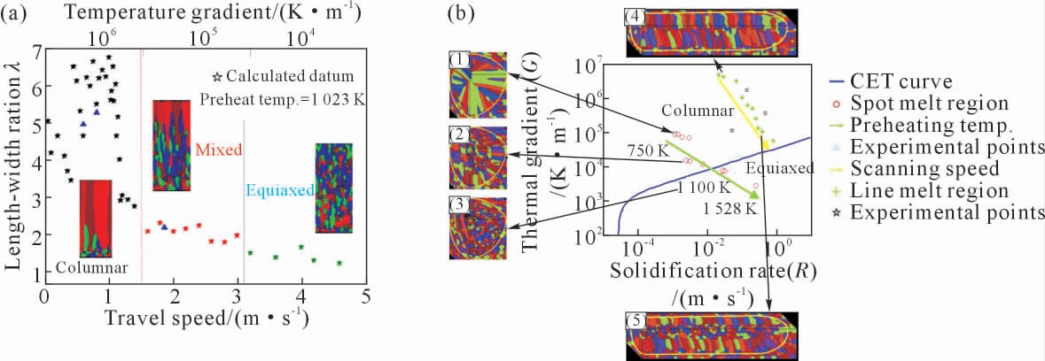
图1 相场法预测随不同工艺参数变化的晶粒形貌:(a)选区电子束熔化制备Ti-6Al-4V 合金过程中晶粒形貌的转变与电子束扫描速度的关系,(b)金属增材制造制备IN718 合金过程中晶粒形貌随温度梯度G,凝固速率R 变化的凝固图谱[73-74]
Fig.1 Variation of grain morphologies with different process parameters predicted by the phase-field method:(a)the transition of grain structure as a function of the electron beam scanning speed during the process of SEBM fabrication of Ti-6Al-4V,(b)solidification map of grain structure of additive manufacturing IN718 varied with thermal gradient G,solidification rate R[73-74]
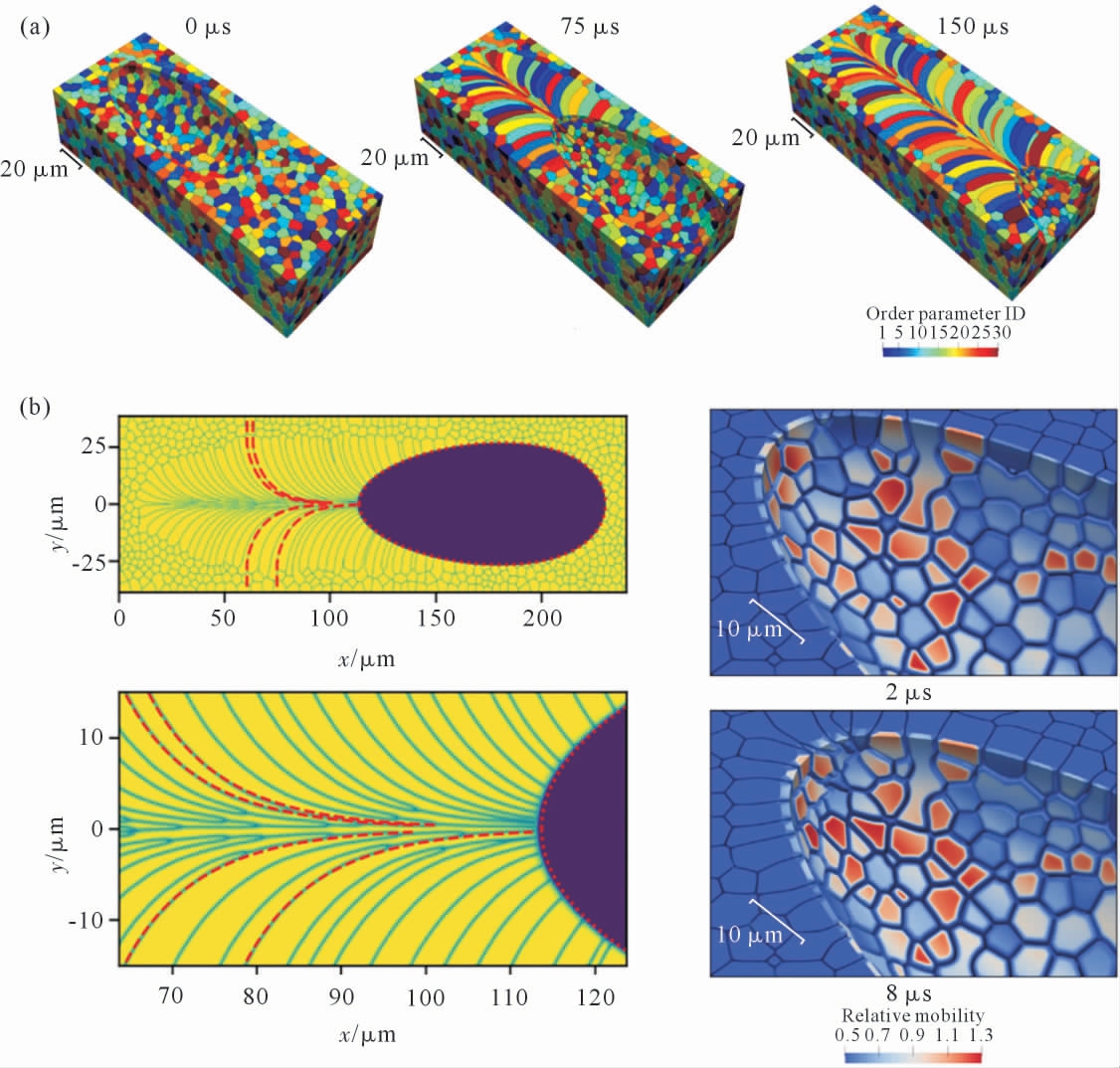
图2 相场模拟的316L 不锈钢金属增材制造过程中晶粒形貌与熔池表面动力学参数的演变:(a)晶粒在不同时刻的形貌演化过程,(b)模拟的晶粒边界迹线与半经验公式结果对比,(c)熔池表面相对界面迁移率(μ(n)/μ0)随时间的变化[75]
Fig.2 Evolution of grain morphology and kinetic parameter variation during metal additive manufacturing of 316L stainless steel according to phase-field simulations:(a)evolution of grain morphology at different moments,(b)comparison between simulated grain boundary trajectory and the result from semi-empirical formula,(c)variations in the value of relative mobilities(μ(n)/μ0)along the melt pool surface over time[75]
2.1.2 多相多序参量相场模型
多相多序参量相场模型在传统晶粒长大相场模型的基础上考虑了液相甚至是气相。因此,除了可以模拟晶粒形貌演化过程外还可模拟孔洞等缺陷的形成,以及用于探究不同工艺参数对孔隙率、致密度的影响。
Yang 等[76]采用多个序参量分别表示固、液两相和不同晶粒取向, 考虑了熔池中的热-熔体流动,同时耦合了形核模型来模拟非均质形核, 模拟了3层3 道选区激光熔化(selective laser melting, SLM)过程。 在激光扫描的过程中,晶粒非均匀形核并沿垂直于熔池边界的方向生长。如图3(b~c)所示,随着扫描道数的增加,晶粒“A”部分熔化,再通过外延生长进入第3 道熔池;如图3(b~d)所示,同时可以观察到图3(b~c)中的熔池边界的大晶粒发生粗化、小晶粒消失(白色圆圈区域)。 当进行第2 层激光扫描时,第1 层部分晶粒发生重熔(见图3(e)蓝色方框区域);进行第3 层扫描时,晶粒的取向发生改变(见图3(e~f)中红色箭头)。 从模拟结果可知,该模型可以模拟多层多道扫描策略下的晶粒形核长大、竞争生长、外延生长、晶粒重熔以及晶粒粗化等现象,但其不足在于该模型没有考虑两相之间的溶质扩散,而两相之间的成分差也会影响晶粒的生长。
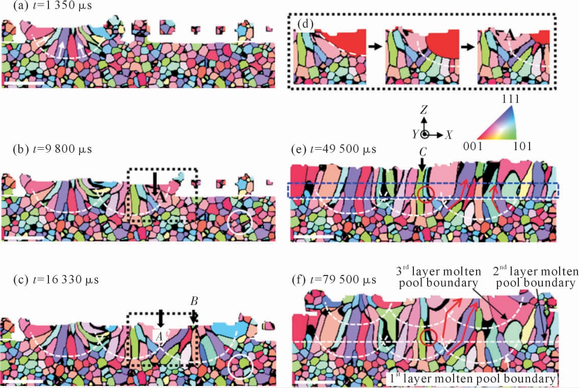
图3 相场模拟的SLM 过程中XZ 截面晶粒演化:(a)第1 层第1 轨道,(b)第1 层第2 轨道,(c)第1 层第3 轨道,(d) (c)中黑色虚线框内的晶粒演化,(e)扫描第2 层后,(f)扫描第3 层后。 白色虚线曲线表示第1 层和第3 层扫描轨迹的熔池边界,白色虚线直线表示第2 层第1 轨道的熔池边界。 (b)和(c)中白色圆圈的晶粒形貌说明了基板中晶粒的粗化,(e)和(f)中红色圆圈的晶粒形貌说明了第3 层扫描时第2 层未重熔区域的晶粒演化。 (e)和(f)中的红色箭头表示晶粒生长方向[76]
Fig.3 Grain evolution in the XZ cross section during the phase-field simulated SLM process:(a)1st track in the 1st layer,(b)2nd track in the 1st layer,(c)3rd track in the 1st layer,(d)grain evolution in the black dashed box in(c),(e)after scanning the 2nd layer,(f)after scanning the 3rd layer.The white dashed curves represent the molten pool boundaries of the scanning tracks in the 1st and 3rd layers,and the white dashed straight line represents the molten pool boundary of the 1st track in the 2nd layer.The grain morphologies in the white circles in(b)and(c)illustrate the grain coarsening in the substrate,and the grain morphologies in the red circles in(e)and(f)illustrate the grain evolution in the unremelted region of the 2nd layer during the 3rd layer scanning[76]
Lu 等[77]发展了多相多序参量相场模型来模拟多层多道粉床增材制造过程。 该模型采用多个序参量表示晶粒取向以及气、固、液3 相,同时引入保守场变量来表示密度。 该模型不仅可以描述晶粒形貌的演化过程,还可以模拟缺陷的形成过程。如图4所示, 该工作模拟了多层多道激光粉床增材制造过程,从(a)到(e)扫描层数逐渐增加。随着激光的扫描,熔池不断移动,未熔化区域出现了固态烧结现象,部分熔化区域发生了晶粒长大, 同时也能观察到局部熔化孔隙、球化孔隙、孔洞等缺陷。 基于相场模拟结果,Lu 等探究了不同激光功率以及扫描速率对熔池尺寸、孔洞以及晶粒形貌的影响。 然而,该模型忽略了流体对流的影响, 只适用于低或中等激光功率的工艺过程。
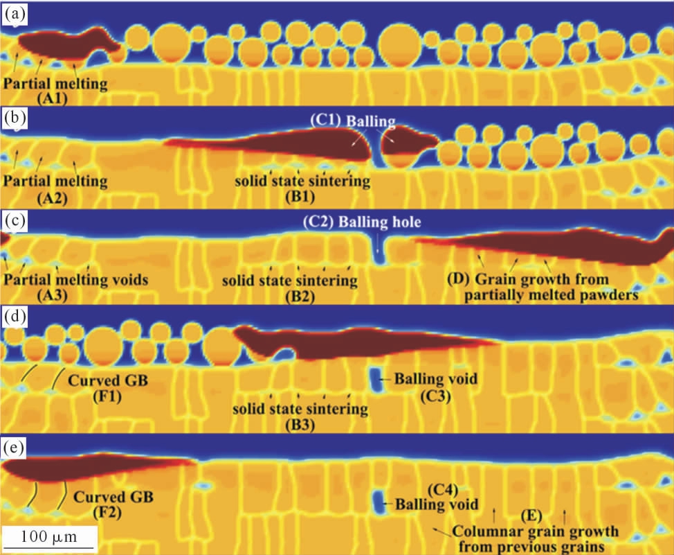
图4 增材制造过程的二维相场模拟结果:(a~c) 第一层的扫描方向为从左到右, 依次为起始、中段和末端,(d~e)第二层的扫描方向为从右到左,依次为中段和末端[77]
Fig.4 2-dimensional phase-field simulation results of the additive manufacturing process:(a~c)beginning,middle and end of the first layer.The scanning direction is from the left side to the right side,(d~e)middle and end of the second layer.The scanning direction is from the right side to the left side[77]
Yang 等[78-80]采用多个序参量表示粉末颗粒以及固液气三相, 发展了粉末增材制造的热—熔体—微结构耦合的非等温相场模型, 模拟了选区激光熔化粉末增材制造过程,揭示了熔池内部晶粒取向、晶粒形状等微观结构演化、 气孔形成与热束扫描参数之间的关联。 图5 所示为选区激光熔化微结构与激光束功率P、扫描速度v 之间的关系。 由图5(a)可以看出,致密度等值线并不沿着直线P/v 方向延伸,表明热束的比能量P/v 并不能完全精确预测微结构特征。 但对图5(a)的数据进行近似处理发现:当P 和v满足P-0.25v-100>0 时, 选区熔化可获得大于90%的致密度。 图5(b)所示为选区熔化生成的几种典型的微结构;图5(b1~b2)所示为倾斜柱状晶粒,并伴有少量气孔;图5(b3~b5)所示为柱状晶粒,但存在大量不规则气孔;从图5(b6)可见选区未发生大面积熔化,熔池间断;从图5(b7)可见选区无熔化。 该工作模拟得到的倾斜柱状晶粒和无规则气孔等微结构特征,与实验结果相对吻合,如图5(c~e)所示。
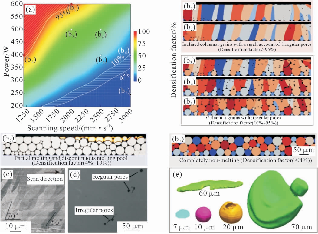
图5 不同扫描参数选区熔化316L 不锈钢粉末的致密度和微结构信息:(a)致密度随热束功率和扫描速度的变化分布图,(b1~b7)不同热束扫描参数对应的微结构形貌,其中(b1)扫描速度为2000mm/s,激光功率为600W,(b2)扫描速度为1250 mm/s,激光功率为400 W,(b3)扫描速度为2 000 mm/s,激光功率为500 W,(b4)扫描速度为2 500 mm/s,激光功率为500 W,(b5)扫描速度为2 500 mm/s,激光功率为400 W,(b6)扫描速度为3 000 mm/s,激光功率为400 W,(b7)扫描速度为3 000 mm/s,激光功率为250 W,(c)倾斜柱状晶粒,(d~e)不同尺寸的规则/ 不规则气孔[80]
Fig.5 Densification factor and microstructure of selective melted 316L stainless steel powder under different scanning parameters:(a)distribution of structural densification factor with heat beam power and scanning speed,(b1~b7)microstructure under different scanning parameters,(b1)scanning speed is 2 000 mm/s and laser power is 600 W,(b2)scanning speed is 1 250 mm/s and laser power is 400 W,(b3)scanning speed is 2 000 mm/s and laser power is 500 W,(b4)scanning speed is 2 500 mm/s,laser power is 500 W,(b5)scanning speed is 2 500 mm/s,laser power is 400 W, (b6)scanning speed is 3 000 mm/s,laser power is 400 W and (b7)scanning speed is 3 000 mm/s,laser power is 250 W,(c)inclined columnar grain,(d~e)regular/irregular pores with different sizes[80]
2.2 连续相场
在金属增材制造制备过程中, 熔池内部凝固速度极快,处于强烈非平衡状态,溶质原子在固相中的固溶度远高于平衡状态,形成过饱和固溶体,对工件的性能以及后续热处理工艺的选择有很大影响[4]。因此考虑凝固过程中熔池内部浓度的变化, 对增材制造过程的非平衡凝固机理进行研究至关重要。 下面对连续相场模型在增材制造中的应用进行了总结,以下根据相场模型类型进行依次介绍。
2.2.1 Karma 相场模型
在增材制造微结构模拟中应用较早的是Karma相场模型。 该模型主要用于模拟熔池局部区域枝晶形貌的演化及溶质浓度分布, 并将获得的定量微结构信息与实验数据进行对比验证。 Fallah 等[81]首先将Karma 相场模型应用到激光能量沉积TiNb 合金中, 模拟熔池局部不同区域的二维枝晶形貌演化及溶质浓度分布。 随后Ghosh 等[82-83]同样采用Karma相场模型对激光粉床熔化(laser powder bed fusion,L-PBF)制备NiNb 合金的凝固过程进行了二维[82]和三维[83]相场模拟,模拟结果如图6(a~b)所示。 一次枝晶间距的理论值可以通过不同长度尺度参数乘积的幂方计算[84]。 如图6(d)所示,相场模拟得到的三维一次枝晶间距比二维一次枝晶间距更小, 且位于2 个不同理论数值的中间, 结果表明相场模拟的三维一次枝晶间距更接近理论值。 同时将相场模型预测的不同维度下的溶质偏析系数以及平衡分配系数进行对比(图6(c)),从图中可以看出,尽管Karma 模型消除了界面厚度造成的数值溶质截留影响, 仍会出现物理溶质截留现象, 这表明激光粉床熔化的凝固过程偏离平衡状态。 Sahoo 等[85]进一步发展了Karma相场模型, 将其耦合有限元求解的温度场用于模拟电子束粉床熔化(electron beam additive manufacturing, EBMA) Ti-6Al-4V 凝固过程的微结构演化,得到了不同温度梯度、 扫描速率下枝晶形貌及溶度分布。 不足的是该模型假设界面处于局部平衡状态且忽略了固相的扩散。 随后,Keller 等[86]通过有限元方法求解热历史模型获得了激光熔池的温度分布,熔池表面温度与Inconel 625 上的原位热图测量结果一致。 随后从温度场中提取凝固参数(如温度梯度、冷却速率等)分别代入DICTRA 和Karma 相场模型中模拟了NiNb 合金激光粉床熔化过程中熔池局部微结构演化。 图7(a)为DICTRA 模拟预测的γ 相成分分布随与二次枝晶核距离的变化,而图7(b)为相场模拟的胞状晶浓度分布。 从图中可以看出相场法模拟的Nb 元素分布与DICTRA 存在明显差异。 这是因为DICTRA 是一维模拟,而相场法可以进行二维模拟,考虑界面曲率以及溶质截留的影响,Karma相场模型模拟的结果更加接近实际值。此外,该工作将模拟得到的一次枝晶间距与Hunt 解析解以及Kurz-Fisher 解析解进行对比。如图7(c)所示,结果吻合较好。 Liu 等[87]将Karma 相场模型与热晶格Boltzmann 方法相结合模拟熔池局部区域传热和流体流动下的微结构演变, 并将其应用到了激光粉床熔化制备Al10Si 合金中,揭示了二次枝晶臂形成的微观机理。
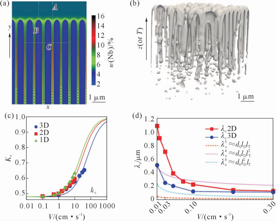
图6 Karma 相场模型在激光粉床熔化Ni-Nb 合金中的应用:(a)二维模拟结果,(b)三维模拟结果,(c)不同维度相场模拟的溶质偏析系数对比,(d)相场模拟的一次枝晶间距与不同比例几何模型预测结果的对比[82-83]
Fig.6 Applications of Karma's phase-field model in L-PBF Ni-Nb alloy:(a)two-dimensional simulation results,(b)three-dimensional simulation results,(c)comparison of solute segregation coefficients of phase field simulation in different dimensions,(d)phase-field simulated cell spacing data compared with different scaling predictions[82-83]
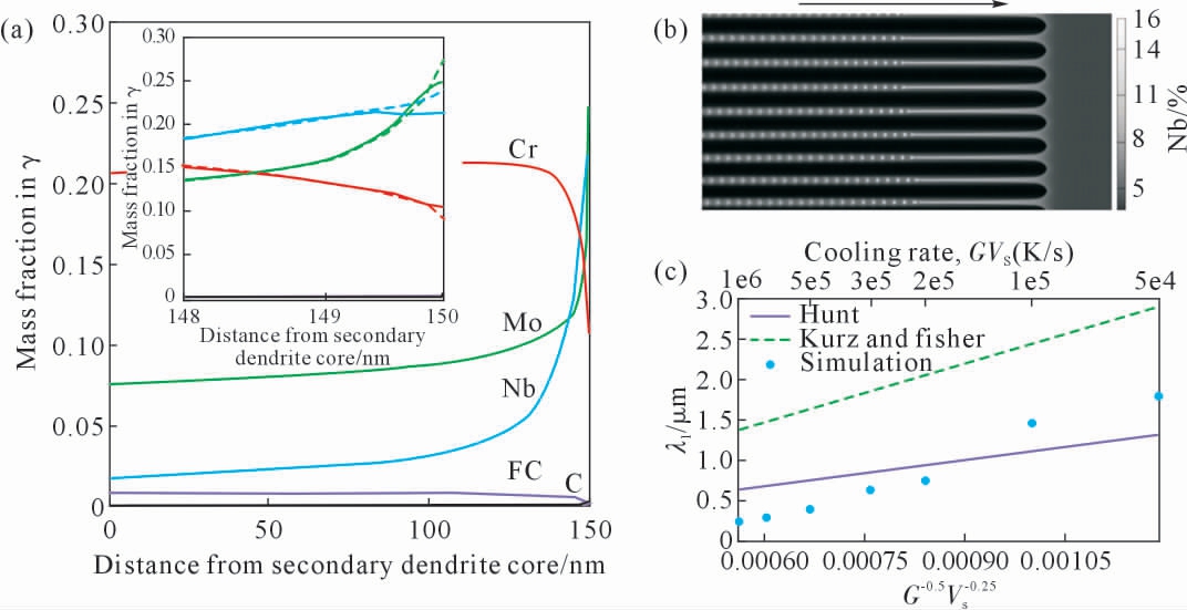
图7 激光粉床熔化Ni-4%Nb(质量分数)合金DICTRA 及相场模拟结果:(a)DICTRA 模拟预测γ 相成分分布随与二次枝晶核距离的变化,(b)相场模拟Ni-4%Nb(质量分数)合金在凝固速率为25 mm/s 时生长1.3 ms 后的胞状结构,(c)相场模拟一次枝晶间距与解析模型的对比[86]
Fig.7 DICTRA simulation and phase field simulation of L-PBF Ni-4%Nb(mass fraction)alloy:(a)composition profiles in γ as a function of distance from the secondary dendrite core predicted by DICTRA simulation,(b)cellular microstructure in Ni-4%Nb(mass fraction)alloy predicted by phase-field simulation after 1.3 ms of growth with Vs=25 mm/s,(c)comparison of primary dendrite arm spacing measured from simulated microstructures with analytical models[86]
Karma 相场模型适用于二元合金接近平衡状态凝固过程的定量模拟, 获得不同工艺参数下的枝晶形貌、一次枝晶间距以及溶质偏析等。 但Karma 相场模型加入反溶质截留项是为了消除界面变宽造成的化学势跳跃,使模拟结果接近平衡状态。 因此,尽管Karma 相场模型模拟增材制造凝固过程中微结构演化时出现了溶质截留现象, 但无法定量描述增材制造过程产生的溶质截留, 以至于无法准确描述浓度场的分布[82-83]。
2.2.2 WBM 相场模型
Karma 相场模型在应用时大多未考虑熔池中温度场的演化且局限于熔池局部区域的微结构演化。Acharya 等[88]将WBM 模型中相场方程与菲克第二定律相结合,同时耦合热传导方程,预测了选区激光熔化IN718 合金(简化为二元合金)凝固过程中熔池不同位置截面枝晶形貌及浓度场演化(图8(a~b)),并将模拟的熔池表面微结构形貌(图8(c))与实验数据(图8(d))进行对比,结果显示枝晶的生长方向与实验结果吻合较好。 此外, 相场模拟的一次枝晶间距、微观偏析也与实验数据吻合较好。 然而,为了获得非平衡过程中溶质偏析信息, 该工作通过连续生长模型(continuous growth model, CGM)[89]的关系式得到了溶质偏析系数, 从而分别获得溶质原子在液相和固相中的浓度,并以此判断溶质偏析的程度,本质上并不是通过相场模拟获得非平衡状态下准确的浓度分布。
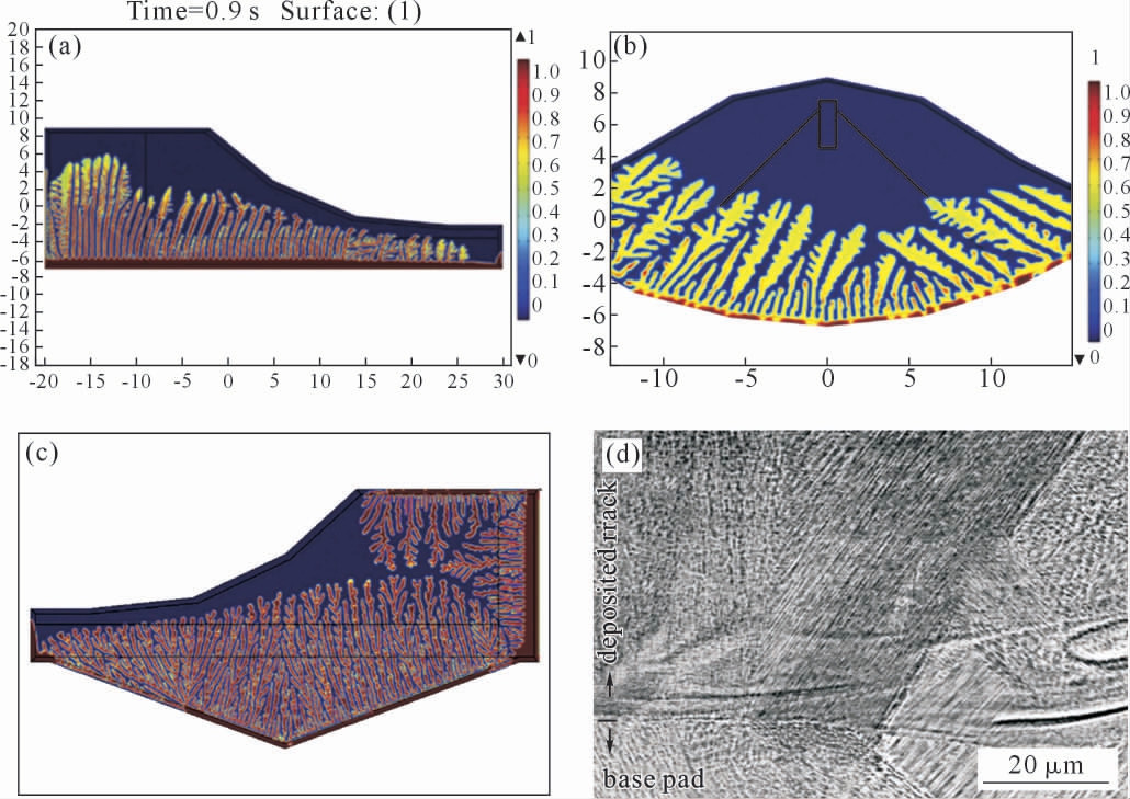
图8 激光粉床熔化制备IN718 合金过程中相场模型预测熔池区域不同截面微结构形貌与实验结果对比:(a)纵向截面微结构相场分布,(b)垂直截面微结构相场分布,(c) 横向横切面显示出过冷度较高时的树枝状结构,(d) 浓度等高线观察到的树枝状结构[88]
Fig.8 Comparison of phase-field predicted microstructure morphologies along different cross sections in the melt pool region and the corresponding experimental results during the L-PBF IN718 process:(a)longitudinal cross section colored according to phase field(f=0 indicates liquid,f=1 indicates solid)showing dendritic structure,(b)transverse cross section colored according to phase field(f=0 indicates liquid,f=1 indicates solid)showing dendritic structure for higher undercooling,(c)transverse cross section showing dendritic structure for higher undercooling,(d)dendritic structure observed from concentration contour[88]
2.2.3 多相场模型
Karma 相场模型以及Acharya 等的工作局限于二元合金, 而实际的增材制造用合金大多是多元合金。 针对这一问题,Park 等[90]采用基于多相场模型[68]开发的MICRESS 软件模拟了激光粉床熔化制备多元合金AlSi10Mg 熔池局部三维形貌演化。 所模拟的凝固枝晶取向与实验一致, 而且先凝固的枝晶对后凝固枝晶的取向具有很大影响。 此外,Kundin 等[91]基于多相场模型开发了考虑到所有相之间热力学因子差异的定量相场模型,并将模型应用于SLM 制备多组分锰钢过程, 模拟冷却速率为1×10⁵ K/s 时,凝固微结构演化以及元素分布。结果表明,相场模型预测的一次枝晶间距以及锰元素分布与实验数据吻合较好。 虽然多相场模型及基于多相场发展的相场模型适用于多元多相体系,但因其采用了准平衡假设,无法准确描述高冷却速率下增材制造工艺凝固过程的溶质分布,例如冷却速度可达1×10⁷ K/s 的选区激光熔化工艺。
2.2.4 有限界面耗散相场模型
近年来,Steinbach 和Zhang 在多相场模型基础上开发了有限界面耗散相场[70-72]。由于该模型可以描述多元多相体系非平衡状态下微结构演化过程,在金属增材制造中的应用不断增多。 Karayagiz 等[92]将有限元求解的温度场与有限界面耗散相场模型进行弱耦合, 定量模拟了激光粉床熔化NiNb 合金凝固过程中的微结构演化,并将模拟得到的枝晶形貌、一次枝晶间距与实验数据进行对比, 验证模拟的准确性(图9(a))。 此外,该工作对比了有限界面耗散相场模型得到的溶质偏析系数与Ghosh 等[82]采用Karma相场模型模拟的溶质偏析系数(图9(b)),结果表明有限界面耗散模型能更准确地描述非平衡过程。 同时该工作通过大量模拟获得了以温度梯度和冷却速率为变量的凝固图谱以及不同线能量密度、 不同冷却速率下的枝晶形貌(图9(c))。 O’Toole 等[93]提出了一种多尺度多物理模拟方法,结合介观尺度的有限界面耗散模型与计算流体动力学计算的宏观温度场(图10(a))模拟了激光粉床熔化Al-10%Si(质量分数)的凝固微结构演化过程(图10(b~c))。Nomoto 等[94]分别采用多相场模型和有限界面耗散相场模型对多元镍合金(Ni(Bal.)-Al-Co-Cr-Mo-Ta-Ti-W-C)激光粉床熔化过不同冷速下等轴晶和柱状晶的生长进行了模拟, 发现处于准平衡状态的一次枝晶间距与非平衡状态的结果存在差距。
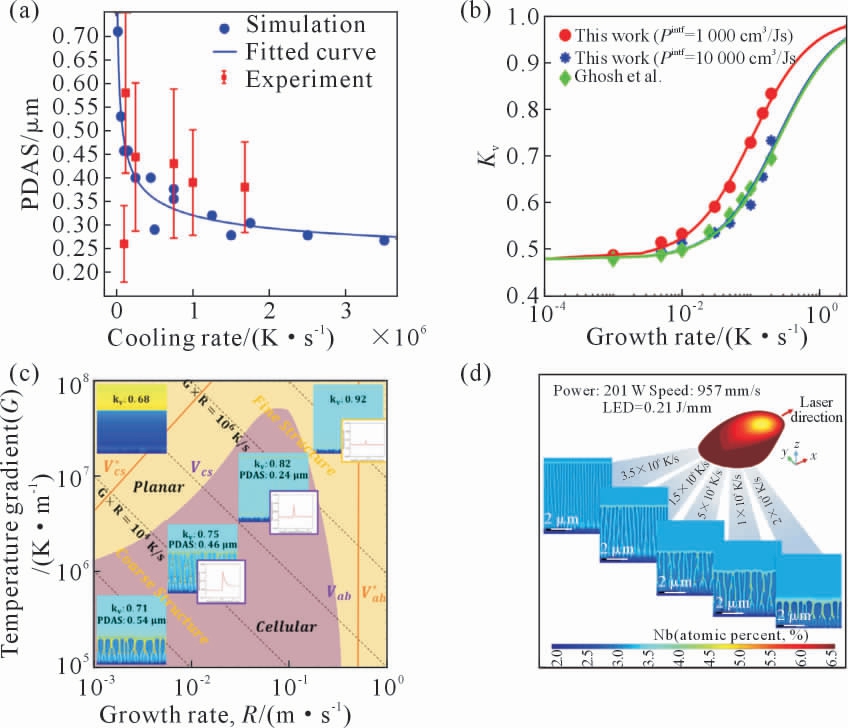
图9 有限界面耗散相场模型在Ni-Nb 合金中的应用:(a)相场模拟的一次枝晶间距(PDAS)随冷却速率的增加而减少,(b)有限界面耗散相场模型模拟的溶质偏析系数Kv 与Ghosh 等的模拟结果进行对比,(c)不同温度梯度、冷却速率下的形貌、胞状偏析结构以及微观偏析变化,(d)高线能量密度条件下沿熔池边界的不同冷却速率下胞状结构和尺寸的变化[92]
Fig.9 Applications of phase-field model with finite interface dispassion in Ni-Nb alloy:(a)the calculated primary dendrite arm spacing(PDAS)reduced as the cooling rate increased,(b)comparison between the simulated segregation coefficients Kv from Ghosh et al.(conventional PF model)and this work(finite interface dissipation PF model)in the quasi-binary Ni-Nb alloy,(c)the variation in morphology,size of cellular segregation structure,and microsegregation as a function of growth rate and temperature gradient,(d)variation in the cellular structure and size at varying cooling rates along the melt pool boundary under high LED condition[92]
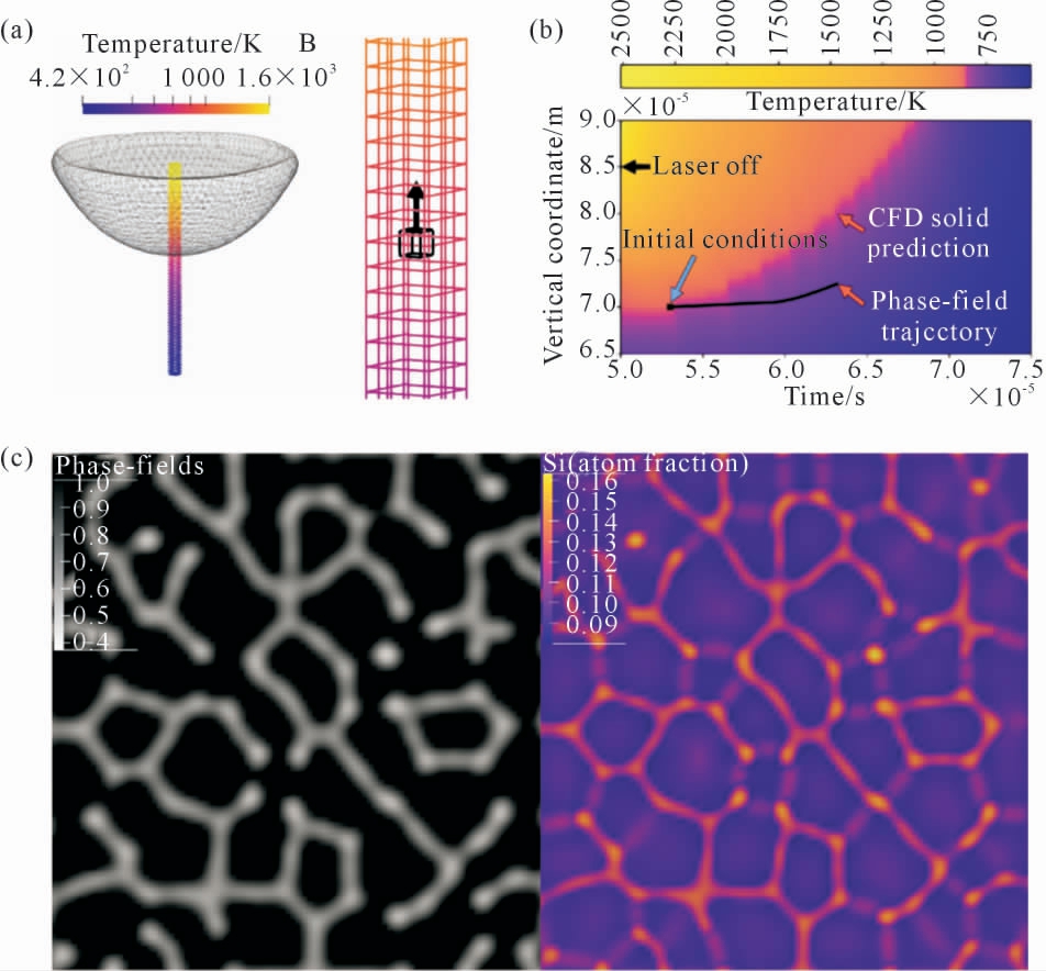
图10 有限界面耗散相场模型在Al-Si 合金中的应用:(a)凝固过程温度场分布,(b)有限界面耗散相场模型模拟xz 截面胞状结构的相场分布及浓度场分布,(c)PF 模拟过程中形成的微孔结构[93]
Fig.10 Application of the phase-field model with finite interface dispassion in Al-Si alloy:(a)temperature field distribution,(b)phase-field simulation results of the phase field distribution and concentration field distribution of the cell structure through the xz-plane,(c)microcellular structure formed during PF simulations,sliced through the xz-plane of the simulation domain,0.2 μm below the solidification front[93]
有限界面耗散相场模型适用于任意热力学状态的相变微结构演变过程, 同时可以应用于多元多相体系的定量模拟。 但考虑到原始有限界面耗散相场模型为抛物线型, 无法重现在高凝固速率下的完全溶质截留现象[95-98],限制了其在高凝固速率选区激光熔化过程中的应用。 中南大学张利军课题组[99]尝试修正有限界面耗散相场中用于描述界面内溶质再分配过程的动力学参数, 初步构建了双曲线型有限界面耗散相场模型, 很好地重现了高凝固速率下的完全溶质截留现象, 进一步拓宽了有限界面耗散相场模型的应用范围。
3 结论与展望
本文详细综述了金属增材制造领域相场模型的发展及其在微结构演变模拟中的应用现状,探讨了不同相场模型在金属增材制造领域应用的优势与局限性。 尽管近年来相场法针对金属增材制造过程中的晶粒、粉末颗粒、枝晶形貌以及缺陷等演化过程取得了一定的进展,但仍处于初级阶段。 为了实现工业合金增材制造过程微结构演变的定量模拟乃至高性能增材制造合金设计,仍存在较多科学问题亟待解决:
(1)适用于增材制造过程的定量相场模型。 定量的相场模型是实现微结构演变定量模拟的前提。 增材制造的凝固过程中冷却速率大,合金处于非平衡状态甚至于极端非平衡状态,因此亟需开发适用于非平衡快速凝固的定量相场模型。目前,Karma 相场模型和传统的多相场模型无法定量描述非平衡过程中的浓度分布。 有限界面耗散相场模型可以描述非平衡的相变过程,但其抛物线形式无法描述高凝固速率的完全溶质截留现象[98]。因此,进一步改进有限界面耗散相场模型(如:双曲线型有限界面耗散相场模型[99]),使其能适用于更加宽广的凝固速率范围,有望获得适用于增材制造过程的定量相场模型。
(2)耦合多物理场的跨尺度微结构模拟。 增材制造过程涉及温度场、流场、相场、浓度场等多个物理场, 仅考虑其中的一个或几个不足以定量描述增材制造过程合金的微结构演变。 但这些物理场的动力学时空尺度具有几个数量级的差异,例如:温度场的热传导过程是宏观现象, 而浓度场的溶质迁移过程则是介观尺度。因此,有必要进行耦合多物理场的跨尺度微结构模拟。目前,已有研究将温度场与连续相场模型以弱耦合的方式模拟熔池内部微结构的演化过程[85-86,92-93],但尚未有研究可以使用强耦合的方式同时求解跨尺度的多个物理场方程。 值得一提的是,目前采用自适应网格划分的有限元求解算法已较为成熟,结合MPI(massage passing interface)并行[79]和GPU (graphics processing unit)[100]加速等手段,或为实现耦合多物理场的跨尺度模拟提供了可行的解决方案。
(3)增材制造多元合金的高效设计。 为了获得高性能的增材制造合金,构建其“成分-工艺-微结构-性能” 定量关系具有重要意义。 相场法耦合多物理场可以实现增材制造多元合金微结构演变的定量模拟,进而建立合金“成分-工艺-微结构”的定量关系。 而对于目标合金“微结构-性能”的定量关系,则可采用机器学习结合实验数据来实现其高效建立[101-102]。 因此,机器学习与相场法相结合有望加速构建“成分-工艺-结构-性能”的定量关系,实现增材制造多元合金的高效设计。
[1] 卢秉恒.增材制造技术——现状与未来[J]. 中国机械工程,2020,31(1):19-23.LU B H. Additive manufacturing-current situation and future[J].China Mechanical Engineering,2020,31(1):19-23.
[2] ABDULHAMEED O,AL-AHMARI A,AMEEN W,et al.Additive manufacturing challenges,trends,and applications[J].Advances in Mechanical Engineering,2019,11(2):1-27.
[3] 卢秉恒,李涤尘. 增材制造(3D 打印)技术发展[J]. 机械制造与自动化,2013,42(4):1-4.LU B H,LI D C.Development of the additive manufacturing (3D printing)technology[J].Machine Building & Automation, 2013,42(4):1-4.
[4] DEBROY T,WEI H L,ZUBACK J S,et al.Additive manufacturing of metallic components-process, structure and properties[J].Progress in Materials Science,2018,92:112-224.
[5] DEBROY T, MUKHERJEE T, MILEWSKI J O, et al. Scientific,technological and economic issues in metal printing and their solutions[J].Nature Materials,2019,18:1026-1032.
[6] DEBROY T,MUKHERJEE T,WEI H L,et al.Metallurgy,mechanistic models and machine learning in metal printing[J]. Nature Reviews Materials,2021,6:48-68.
[7] BOSE S,KE D X,SAHASRABUDHE H,et al.Additive manufacturing of biomaterials[J].Progress in Materials Science, 2018,93:45-111.
[8] SHINDE M S, ASHTANKAR K M. Additive manufacturing-assisted conformal cooling channels in mold manufacturing processes[J].Advances in Mechanical Engineering,2017,9(5):1-14.
[9] QI D X,YU H B,LIU M,et al.Mechanical behaviors of SLM additive manufactured octet-truss and truncated-octahedron lattice structures with uniform and taper beams[J].International Journal of Mechanical Sciences,2019,163:105091.
[10] WANG Y M,VOISIN T,MCKEOWN J T,et al.Additively manufactured hierarchical stainless steels with high strength and ductility[J].Nature Materials,2018,17(1):63-71.
[11] 高建宝,李志诚,刘佳,等. 计算辅助高性能增材制造铝合金开发的研究现状与展望[J].金属学报,2023,59(1):87-105.GAO J B, LI Z C, LIU J, et al. Current situation and prospect of computationally assisted design in high-performance additive manufacturing of aluminum alloys: A review[J]. Acta Metallurgica Sinica,2023,59(1):87-105.
[12] WEI H L,KNAPP G L,MUKHERJEE T,et al.Three-dimensional grain growth during multi-layer printing of a nickel-based alloy Inconel 718[J].Additive Manufacturing,2019,25:448-459.
[13] JADHAV S D, DADBAKHSH S, GOOSSENS L, et al. Influence of selective laser melting process parameters on texture evolution in pure copper[J].Journal of Materials Processing Technology,2019,270:47-58.
[14] ANDREAU O, KOUTIRI I, PEYRE P, et al. Texture control of 316L parts by modulation of the melt pool morphology in selective laser melting[J].Journal of Materials Processing Technology,2019,264:21-31.
[15] MARTIN J H, YAHATA B D, HUNDLEY J M, et al. 3D printing of high-strength aluminium alloys[J]. Nature,2017,549:365-369.
[16] MA M M, WANG Z M, WANG D Z, et al. Control of shape and performance for direct laser fabrication of precision large-scale metal parts with 316L stainless steel[J].Optics&Laser Technology,2013,45:209-216.
[17] ABD-ELGHANY K,BOURELL D L.Property evaluation of 304L stainless steel fabricated by selective laser melting[J].Rapid Prototyping Journal,2012,18(5):420-428.
[18] ZHANG B C,DEMBINSKI L,CODDET C.The study of the laser parameters and environment variables effect on mechanical properties of high compact parts elaborated by selective laser melting 316L powder[J].Materials Science and Engineering:A,2013,584:21-31.
[19] WANG P,DENG L,PRASHANTH K G,et al.Microstructure and mechanical properties of Al-Cu alloys fabricated by selective laser melting of powder mixtures[J].Journal of Alloys and Compounds,2018,735:2263-2266.
[20] GUNASEGARAM D R, MURPHY A B, CUMMINS S J, et al.Aiming for Modeling-Assisted Tailored Designs for Additive Manufacturing:TMS 2017 146th Annual Meeting & Exhibition Supplemental Proceedings[C].Berlin: Springer International Publishing,2017:91-102.
[21] COOK P S, MURPHY A B. Simulation of melt pool behaviour during additive manufacturing: Underlying physics and progress[J].Additive Manufacturing,2020,31:100909.
[22] 肖文甲. 激光增材制造镍基高温合金枝晶生长的机理研究[D].长沙:湖南大学,2019.XIAO W J.Mechanism of dendrite growth for laser additive manufacturing of Nickel-base superalloy[D].Changsha:Hunan University,2019.
[23] ABOULKHAIR N T, SIMONELLI M, PARRY L, et al. 3D printing of aluminium alloys:Additive manufacturing of aluminium alloys using selective laser melting[J]. Progress in Materials Science,2019,106:100578.
[24] ZHANG J L,SONG B,WEI Q S,et al.A review of selective laser melting of aluminum alloys: Processing, microstructure, property and developing trends[J].Journal of Materials Science&Technology,2019,35(2):270-284.
[25] BOETTINGER W J, WARREN J A, BECKERMANN C, et al.Phase-field simulation of solidification[J].Annual Review of Materials Research,2002,32(1):163-194.
[26] PROVATAS N, ELDER K. Phase-field methods in materials science and engineering[M].Weinheim: Wiley-VCH Verlag GmbH&Co.KGaA,2010.
[27] GRÁNÁSY L, PUSZTAI T, WARREN J A. Modelling polycrystalline solidification using phase field theory[J].Journal of Physics:Condensed Matter,2004,16(41):R1205.
[28] ODE M,KIM S G,SUZUKI T.Recent advances in the phase-field model for solidification[J].ISIJ International, 2001,41(10):1076-1082.
[29] STEINBACH I.Phase-field models in materials science[J].Modelling and Simulation in Materials Science and Engineering,2009,17(7):073001.
[30] MORDECHAI S. Applications of monte carlo method in science and engineering[M].London:IntechOpen,2011.
[31] LIU Y F,CHENG L F,ZENG Q F,et al.Monte Carlo simulation of polycrystalline microstructures and finite element stress analysis[J].Materials&Design,2014,55:740-746.
[32] WEI H L,ELMER J W,DEBROY T.Three-dimensional modeling of grain structure evolution during welding of an aluminum alloy[J].Acta Materialia,2017,126:413-425.
[33] LIAN Y P,GAN Z T,YU C,et al.A cellular automaton finite volume method for microstructure evolution during additive manufacturing[J].Materials&Design,2019,169:107672.
[34] YIN H, FELICELLI S D. Dendrite growth simulation during solidification in the LENS process[J].Acta Materialia, 2010,58(4):1455-1465.
[35] ZINOVIEVA O, ZINOVIEV A, PLOSHIKHIN V. Three-dimensional modeling of the microstructure evolution during metal additive manufacturing[J].Computational MaterialsScience,2018,141:207-220.
[36] CHEN R,XU Q Y,LIU B C.A modified cellular automaton model for the quantitative prediction of equiaxed and columnar dendritic growth[J]. Journal of Materials Science & Technology, 2014,30(12):1311-1320.
[37] SCHIFF J L. Cellular automata: A discrete view of the world[M].Hoboken:John Wiley&Sons,2011.
[38] TAN J H K, SING S L, YEONG W Y. Microstructure modelling for metallic additive manufacturing:Areview[J].Virtual and Physical Prototyping,2020,15(1):87-105.
[39] GANDIN C A, RAPPAZ M. A 3D Cellular Automaton algorithm for the prediction of dendritic grain growth[J]. Acta Materialia,1997,45(5):2187-2195.
[40] RAPPAZ M,GANDIN C A.Probabilistic modelling of microstructure formation in solidification processes[J].Acta Metallurgica et Materialia,1993,41(2):345-360.
[41] KÖRNER C,MARKL M,KOEPF J A.Modeling and simulation of microstructure evolution for additive manufacturing of metals:A critical review[J].Metallurgical and Materials Transactions A,2020,51:4970-4983.
[42] CHEN L Q,WANG Y Z.The continuum field approach to modeling microstructural evolution[J].JOM,1996,48:13-18.
[43] CHEN L Q. Phase-field models for microstructure evolution[J].Annual Review of Materials Research,2002,32:113-140.
[44] YU F Y,WEI Y H,JI Y Z,et al.Phase field modeling of solidification microstructure evolution during welding[J].Journal of Materials Processing Technology,2018,255:285-293.
[45] MOELANS N,BLANPAIN B,WOLLANTS P.An introduction to phase-field modeling of microstructure evolution[J].Calphad,2008,32(2):268-294.
[46] QIN R S,BHADESHIA H K.Phase field method[J].Materials Science and Technology,2013,26(7):803-811.
[47] TOURRET D, LIU H, LLORCA J. Phase-field modeling of microstructure evolution: Recent applications,perspectives and challenges[J].Progress in Materials Science,2022,123:100810.
[48] KARMAA,OLABI A G.Phasefieldmethods[M]//Reference Module in Materials Science and Materials Engineering.Amsterdam:Elsevier,2016.
[49] MOELANS N, BLANPAIN B, WOLLANTS P. An introduction to phase-field modeling of microstructure evolution[J].Calphad,2008,32(2):268-294.
[50] CHEN L Q, KHACHATURYAN A G. Computer simulation of structural transformations during precipitation of an ordered intermetallic phase[J].Acta Metallurgica et Materialia,1991,39(11):2533-2551.
[51] WANG Y, CHEN L Q, KHACHATURYAN A G. Kinetics of strain-induced morphological transformation in cubic alloys with a miscibility gap[J].Acta Metallurgica et Materialia, 1993,41(1):279-296.
[52] CHEN L Q. A novel computer simulation technique for modeling grain growth[J].Scripta Metallurgica et Materialia, 1995,32(1):115-120.
[53] CHEN L Q, YANG W. Computer simulation of the domain dynamics of a quenched system with a large number of nonconserved order parameters: The grain-growth kinetics[J]. Physical Review B,1994,50(21):15752-15756.
[54] FAN D,CHEN L Q.Diffusion-controlled grain growth in two-phase solids[J].Acta Materialia,1997,45(8):3297-3310.
[55] KAZARYAN A R,WANG Y Z,DREGIA S A,et al.Grain growth in systems with anisotropic boundary mobility: Analytical model and computer simulation[J]. Physical Review B, 2001, 63(18):184102.
[56] KRILL III C E, CHEN L Q. Computer simulation of 3-D grain growth usingaphase-fieldmodel[J].Acta Materialia,2002,50(12):3059-3075.
[57] MOELANS N,BLANPAIN B,WOLLANTS P.Quantitative analysis of grain boundary properties in a generalized phase field model for grain growth in anisotropic systems[J]. Physical Review B,2008,78(2):024113.
[58] MOELANS N,WENDLER F,NESTLER B.Comparative study of two phase-field models for grain growth[J].Computational Materials Science,2009,46(2):479-490.
[59] LANGER J.Models of pattern formation in first-order phase transitions[M]//GRINSEIN G, MAZENKO G. Directions in condensed matter physics:Memorial volume in honor of shang-keng ma.Singapore:World Scientific,1986:165-186.
[60] HOHENBERG P C, HALPERIN B I. Theory of dynamic critical phenomena[J].Reviews of Modern Physics,1977,49(3):435-479.
[61] WHEELERAA,BOETTINGERWJ,MCFADDENGB.Phase-field model for isothermal phase transitions in binary alloys[J].Physical Review A,1992,45(10):7424-7439.
[62] WHEELERAA,BOETTINGERWJ,MCFADDENGB.Phase-field model of solute trapping during solidification[J]. Physical Review E,1993,47(3):1893-1909.
[63] KIM S G,KIM W T,SUZUKI T.Phase-field model for binary alloys[J].Physical Review E,1999,60(6):7186-7197.
[64] KITTL J A, SANDERS P G, AZIZ M J, et al. Complete experimental test of kinetic models for rapid alloy solidification[J].Acta Materialia,2000,48(20):4797-4811.
[65] KARMA A. Phase-field formulation for quantitative modeling of alloy solidification[J].PhysialReviewLetters,2001,87(11):115701.
[66] KARMA A,RAPPEL W J.Phase-field method for computationally efficient modeling of solidification with arbitrary interface kinetics[J].Physical Review E,1996,53(4):R3017-R3020.
[67] BÖTTGER B,EIKEN J,STEINBACH I.Phase field simulation of equiaxed solidification in technical alloys[J].Acta Materialia,2006,54(10):2697-2704.
[68] STEINBACH I, PEZZOLLA F, NESTLER B, et al. A phase field concept for multiphase systems[J].Physica D:Nonlinear Phenomena,1996,94(3):135-147.
[69] ECHEBARRIA B, FOLCH R, KARMA A, et al. Quantitative phase-field model of alloy solidification[J].Physial Review E,2004,70(6):061604.
[70] STEINBACH I,ZHANG L J,PLAPP M.Phase-field model with finite interface dissipation[J].Acta Materialia,2012,60(6-7):2689-2701.
[71] ZHANG L J, STEINBACH I. Phase-field model with finite interface dissipation:Extension to multi-component multi-phase alloys[J].Acta Materialia,2012,60(6-7):2702-2710.
[72] ZHANG L J, STRATMANN M, DU Y, et al. Incorporating the CALPHAD sublattice approach of ordering into the phase-field model withfiniteinterfacedissipation[J].Acta Materialia,2015,88:156-169.
[73] LIU P W,JI Y Z,WANG Z,et al.Investigation on evolution mechanisms of site-specific grain structures during metal additive manufacturing[J].Journal of Materials Processing Technology, 2018,257:191-202.
[74] LIU P W,WANG Z,XIAO Y H,et al.Insight into the mechanisms of columnar to equiaxed grain transition during metallic additive manufacturing[J].Additive Manufacturing,2019,26:22-29.
[75] CHADWICK A F, VOORHEES P W. The development of grain structure during additive manufacturing[J]. Acta Materialia, 2021,211:116862.
[76] YANG M, WANG L, YAN W T. Phase-field modeling of grain evolutions in additive manufacturing from nucleation, growth, to coarsening[J].npj Computational Materials,2021,7:56.
[77] LU L X, SRIDHAR N, ZHANG Y W. Phase field simulation of powder bed-based additive manufacturing[J].Acta Materialia,2018,144:801-809.
[78] YANG Y Y W, OYEDEJI T D, KÜHN P, et al. Investigation on temperature-gradient-driven effects in unconventional sintering via non-isothermal phase-field simulation[J].Scripta Materialia,2020,186:152-157.
[79] YANG Y Y W,RAGNVALDSEN O,BAI Y,et al.3D non-isothermal phase-field simulation of microstructure evolution during selective laser sintering[J].npj Computational Materials,2019,5:81.
[80] 杨阳祎玮,易敏,胥柏香. 粉末增材制造微结构的非等温相场模拟[J].中南大学学报(自然科学版),2020,51(11):3019-3031.YANG Y Y W,YI M,XU B X.Non-iosthermal phase-field simulation of microstructure in power-based additive manufacturing[J].Journal of Central South University(Science and Technology),2020,51(11):3019-3031.
[81] FALLAH V,AMOOREZAEI M,PROVATAS N,et al.Phase-field simulation of solidification morphology in laser powder deposition of Ti-Nb alloys[J].Acta Materialia,2012,60(4):1633-1646.
[82] GHOSH S,MA L,OFORI-OPOKU N,et al.On the primary spacing and microsegregation of cellular dendrites in laser deposited Ni-Nb alloys[J].Modelling and Simulation in Materials Science and Engineering,2017,25(6):065002.
[83] GHOSH S,OFORI-OPOKU N,GUYER J E.Simulation and analysis of γ-Ni cellular growth during laser powder deposition of Ni-based superalloys[J].Computational Materials Science, 2018,144:256-264.
[84] DANTZIG J A,RAPPAZ M . Solidification[M].Switzerland:EFPL Press,2009.
[85] SAHOO S, CHOU K. Phase-field simulation of microstructure evolution of Ti-6Al-4V in electron beam additive manufacturing process[J].Additive Manufacturing,2016,9:14-24.
[86] KELLER T,LINDWALL G,GHOSH S,et al.Application of finite element, phase-field, and CALPHAD-based methods to additive manufacturing of Ni-based superalloys[J]. Acta Materialia, 2017,139:244-253.
[87] LIU D H, WANG Y. Mesoscale multi-physics simulation of rapid solidification of Ti-6Al-4V alloy[J].Additive Manufacturing,2019,25:551-562.
[88] ACHARYA R, SHARON J A, STAROSELSKY A. Prediction of microstructure in laser powder bed fusion process[J].Acta Materialia,2017,124:360-371.
[89] AZIZ M J, KAPLAN T. Continuous growth model for interface motion during alloy solidification[J].Acta Metallurgica,1988,36(8):2335-2347.
[90] PARK J, KANG J H, OH C S. Phase-field simulations and microstructural analysis of epitaxial growth during rapid solidification of additively manufactured AlSi10Mg alloy[J]. Materials &Design,2020,195:108985.
[91] KUNDIN J,RAMAZANI A,PRAHL U,et al.Microstructure evolution of binary and multicomponent manganese steels during selective laser melting: Phase-field modeling and experimental validation[J].Metallurgical and Materials Transactions A, 2019,50:2022-2040.
[92] KARAYAGIZ K, JOHNSON L, SEEDE R,et al.Finite interface dissipation phase field modeling of Ni-Nb under additive manufacturing conditions[J].Acta Materialia,2020,185:320-339.
[93] O’TOOLE P I,PATEL M J,TANG C,et al.Multiscale simulation of rapid solidification of an aluminium-silicon alloy under additive manufacturing conditions[J]. Additive Manufacturing, 2021,48:102353.
[94] NOMOTO S, SEGAWA M, WATANABE M. Non- and quasi-equilibrium multi-phase field methods coupled with CALPHAD database for rapid-solidification microstructural evolution in laser powder bed additive manufacturing condition [J].Metals,2021,11(4):626.
[95] YANG X,TANG Y,CAI D,et al. Comparative analysis of different numerical schemes in solute trapping simulations by using the phase-field model with finite interface dissipation[J].Journal of Mining and Metallurgy, Section B: Metallurgy, 2016, 52(1):77-85.
[96] YANG X, ZHANG L J, SOBOLEV S, et al. Kinetic phase diagrams of ternary Al-Cu-Li system during rapid solidification: A phase-field study[J].Materials(Basel),2018,11(2):260.
[97] YANG X,ZHANG L J,DU Y.Phase field modeling of solute trapping in a Al-Sn alloy during rapid solidification[J].Materials Science Forum,2014,794-796:740-745.
[98] ZHANG L J, DANILOVA E V, STEINBACH I, et al. Diffuse-interface modeling of solute trapping in rapid solidification: Predictions of the hyperbolic phase-field model and parabolic model with finite interface dissipation[J].Acta Materialia,2013,61(11):4155-4168.
[99] 杨雄. 合金快速凝固过程的相场模型、 数值模拟和动力学相图[D].长沙:中南大学,2018.YANG X. Phase-field model, numerical simulation and kinetic phase diagram for alloys during rapid solidification process[D].Changsha:Central South University,2018.
[100] YANG S, ZHONG J, WANG K, et al. Insights into complex hexagonal close-packed dendritic growth during alloy solidification aided by GPU-accelerated three-dimensional phase-field simulations:a demo in Mg-Gd alloy[J].Rare Metals,2023,Accepted.
[101]YI W,LIU G C,LU Z,et al.Efficient alloy design of Sr-modified A356 alloys driven by computational thermodynamics and machine learning[J].Journal of Materials Science&Technology,2022,112:277-290.
[102]LIU Q,WU H K,PAUL M J,et al.Machine-learning assisted laser powder bed fusion process optimization for AlSi10Mg: New microstructure description indices and fracture mechanisms[J].Acta Materialia,2020,201:316-328.